1. RF chip test socket
I. Introduction
2. Indicators and functions of RF test socket
3. Composition of RF test socket
4. Working principle of RF radio frequency test socket
5. How to make RF radio frequency test socket
6. Maintenance of RF test socket
I. Introduction
We all know that RF components and RF chips are the core of wireless connections and an important part of the semiconductor industry.
With the emergence of 5G and WIFI6, radio frequency technology has also encountered new challenges and opportunities.
At present, the design and production capabilities of RF components and RF chips are still relatively weak.
With the implementation of the national strategic adjustment policy, more and more resources are invested in the development and production of radio frequency components and chips.
In this process, there is an urgent need to meet the production and testing of RF chips in China.
The difficulties in testing are:
1. The devices under test are getting smaller and smaller, and the testing frequency is getting higher and higher. Many devices are less than 1mm in size.
The test frequency is higher than 40GHZ.
2. Affected by test fixtures and calibration, how to measure accurately is the primary issue faced by manufacturers.
2. Indicators and functions of RF test socket Test indicators:
Standing waves, insertion loss;
Center frequency, bandwidth;
In-band fluctuation, out-of-band suppression, group delay, etc.
What role does the test socket play in testing RF chips:
Generally speaking, RF test sockets can perform testing work during the R&D and low-volume production stages.
Testing is performed manually and the test socket is precisely customized according to the customer's RF chip size and test parameters to ensure the accuracy of the test results.
3. Composition of RF test socket
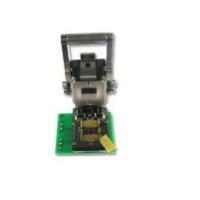
The RF radio frequency test socket is composed of several parts. The first is the test socket shell + test socket conventional probe + RF radio frequency coaxial connector
Most of the structures of the RF radio frequency test socket are similar to ordinary test sockets, except for the coaxial connector.
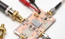
Now we mainly talk about RF connectors. RF connector is a radio frequency coaxial connector, which mainly plays the role of communication radio frequency.
Through the joint efforts of the global communications industry, RF connectors have formed a professional system and international standards.
It is also an essential part of the connector.
4. Working principle of RF radio frequency test socket
The conventional pins of the RF radio frequency test socket still use the corresponding pogo pin probes.
However, since radio frequency signal transmission requires a special medium, the corresponding connector part is also very special.
Our more common RF coaxial connector (RF COAXIAL CONNECTOR) is one of them.
This component will be embedded in the test socket and used for radio frequency conduction during testing.
For the design selection of the RF connector in the corresponding test socket, you can refer to the following (not limited to the following interfaces),
At the same time, when customizing the test socket, you also need to propose the insertion loss and return loss requirements of your own chip to the supplier (i.e. S12/S21 and S11), and you also need to propose your own contact impedance requirements:
BNC is a bayonet type, mostly used for radio frequency connections below 4GHz, and is widely used in instrumentation and computer interconnection. TNC is a threaded connection, similar to BNC in size and other aspects. The operating frequency can reach 11GHz. The threaded type is suitable for vibration environments.
SMA is a threaded connection, the most widely used, with impedances of 50 and 75 ohms. When 50 ohms is used with a soft cable, the frequency is lower than 12.4Ghz, and with a semi-rigid cable, the frequency is up to 26.5GHz. SMB is smaller than SMA. It has an inserted self-locking structure and is used for quick connection. It is often used in digital communications. It is a replacement of L9. It can reach 4GHz with 50 ohms and 2GHz with 75 ohms.
SMC is a threaded connection, others are similar to SMB, have a wider frequency range, and are often used in military or high-vibration environments.
The N-type connector is threaded and uses air as the insulating material. It is low-cost and has a frequency of up to 11GHz. It is commonly used in test instruments and is available in 50 and 75 ohm types. MCX and MMCX connectors are small and are used for dense connections.
BMA is used for blind-mating connections in low-power microwave systems with frequencies up to 18GHz.
5. How to make RF radio frequency test socket
With the current upgrade of high-speed communication standards such as 5G and WIFI6, the demand for RF radio frequency test sockets is increasing and getting higher and higher. The current main RF chips will use aging tests, functional tests, and special tests in extreme environments. testing, so it also puts forward higher testing requirements for RF radio frequency test sockets.
Product design needs to rely on data, including chip size (length, width and thickness), chip spacing, chip shape, the frequency at which the chip needs to run during chip testing, and corresponding insertion loss, return loss and other data. Some RF chips have high power and may need to provide over-current requirements. As we all know, the over-current capability of the test socket pogo pin is less than 1A, so the over-current capability of the chip's power pin also needs to be taken into consideration, otherwise it will affect the full firepower of the chip. open test data.
Socket+ RF coaxial connector (isolation also needs to be considered)
6. Maintenance of RF test socket
The RF test socket requires regular maintenance. It is best to check the contact probe or RF connector with a microscope every 5,000 times of use to check whether there is dirt on the top of the needle and the wear of the needle to ensure that the test socket is always in good condition. test status. If there is dirt, it is recommended to use ultrasonic cleaning equipment, put in high-purity alcohol for ultrasonic cleaning, and then use an air gun for final cleaning to ensure that the test seat is in a dry state to ensure the service life and test performance of the product. If there is slight wear, it will not affect the test. (That is, the test data does not have a large error) and can continue to be used after cleaning. If the damage is serious, the probe and RF connector will need to be replaced before it can continue to be used.


