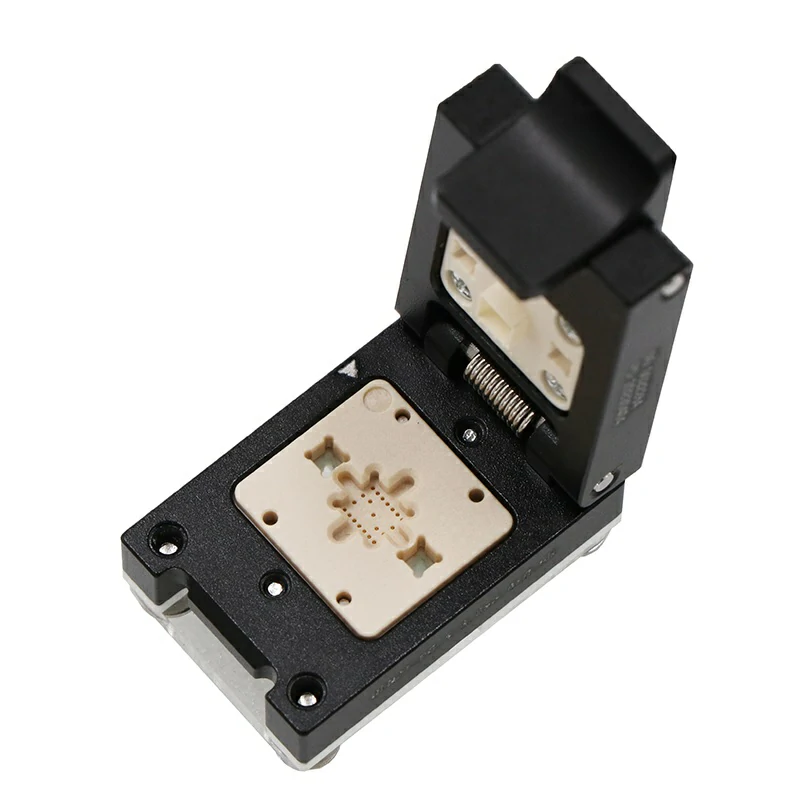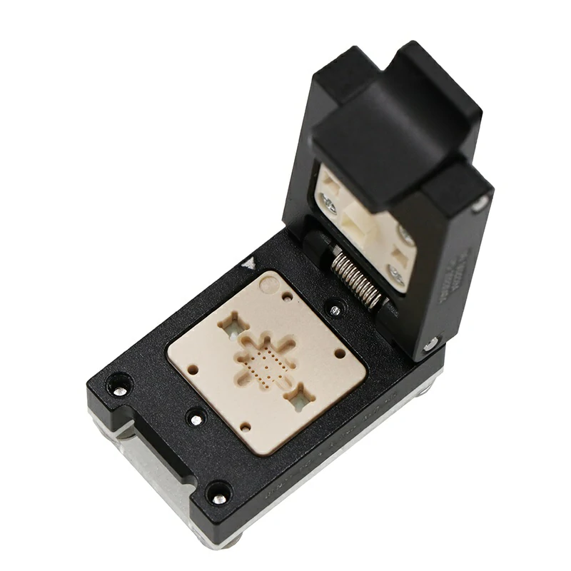


1. Actual requirements:
1.Package: OLGA14 package
2. Number of Pins: 14
3. Number of grounding connections: 0pin
4. Chip type: heart rate sensor chip
5. Test requirements: There are no special electrical requirements for chip testing. A 1.8V and 5V power supply is required. The main problem is that the heart rate module needs to accept the reflected light from the light source synchronously emitted by the device in a dark environment. This requires corresponding design on the test socket. Be careful that the process is not too long. Try to make the light source, reflection source and sensor chip simulate the actual contact between the chip and the skin as much as possible.
2. Demand analysis: In terms of electrical properties, ordinary probes can be matched, mainly for the simulation of the test environment. It is necessary to pay attention to: the color light intensity of the light source and the reflected light source, and the contact situation of the sensor chip. This chip needs to emit green light. It transmits and reflects part of the light to the sensor through the skin simulation block (blue light), which requires the test socket to be in a black box state and be as thin as possible.
3. Production: chip package 5.6mm x 3.3mm x 1.55mm 14-Pin 0.8 pitch, ordinary micro probe, thin design of test seat to match the chip, pressure block to simulate skin blue light block, 2 light sources are reserved inside the test seat The light source hole is enough.
4. Shipping requirements: The interface is designed to meet the test requirements, and the user provides a test board for on-site testing.
MAX30102 heart rate sensor chip OLGA14-0.8 onboard test socket

